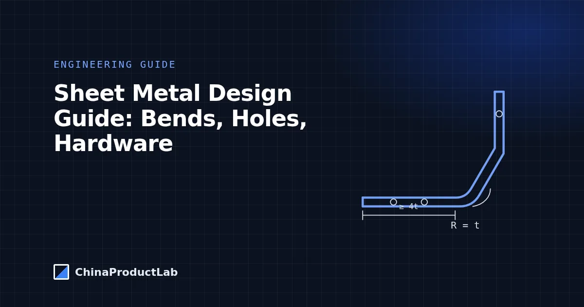
Sheet metal looks simple, which is why it is easy to get wrong: a flange too short for the press brake, holes that distort when the part is bent, an aluminum alloy that cracks on a tight bend, or self-clinching nuts placed where they cannot be installed. These rules of thumb help you design parts that a fabricator can make right the first time. Always confirm with your fabricator’s tooling — die widths and punch radii set the real limits.
Bends
- Inside bend radius: about equal to the material thickness is a common default for mild steel, stainless and 5052 aluminum. Use one radius throughout the part so it can be bent with one tool set.
- Alloy matters: 6061-T6 aluminum tends to crack on tight bends; use 5052 for formed parts, or a larger radius.
- Minimum flange length: the flange must sit on the V-die; a common rule of thumb is around four times the material thickness.
- Bend relief: add relief cuts where a bend ends next to an edge, so the material does not tear.
- Grain direction: bending across the rolling direction reduces cracking risk on tight bends.
Holes and cut-outs
- Keep holes away from bends — a common guideline is at least about 2.5 × thickness plus the bend radius — or they deform into ovals.
- Keep holes at least about 1.5–2 × thickness from edges.
- Hole diameter generally not smaller than the material thickness for clean punching or cutting.
- Use slots or larger clearance holes where parts are assembled across several bends, to absorb tolerance stack-up.
Hardware (PEM and similar)
Self-clinching nuts, studs and standoffs give strong threads in thin sheet. Follow the hardware manufacturer’s data for minimum sheet thickness, hole size and distance to edges and bends — and check that the installation press can reach the location (not inside a closed box section). Install hardware before powder coating, or mask threads.
Tolerances: what to expect
| Feature | Typical capability | Note |
|---|---|---|
| Laser-cut features in one flat plane | Tight (often around ±0.1 mm) | Holes and outlines in the same face are the most accurate |
| Dimensions across one bend | Looser (often a few tenths of a mm) | Material thickness and bend variation add up |
| Dimensions across several bends | Loosest | Tolerances stack — design with slots or adjustment |
| Bend angle | Often around ±0.5–1° | Depends on material and press brake |
Values are typical and fabricator-dependent. Dimension critical features from the same face or a common datum rather than across bends.
Welding and finishing
- Welding distorts thin sheet — use tabs and slots for self-fixturing, and allow for straightening or post-weld machining on precise features.
- Powder coating adds significant thickness: mask threads, grounding points and tight-fitting edges.
- For corrosion resistance without coating, choose galvanized steel, stainless or aluminum — and avoid mixing metals that cause galvanic corrosion.
Send a 3D model with sheet thickness (or a flat pattern) plus a drawing of bends, hardware and finish. More on sheet metal fabrication, choosing metals, or request a quote.