Tolerances are where engineering intent meets manufacturing cost. Drawings with ±0.01 mm on every dimension get expensive quotes — or optimistic suppliers who quietly ignore them. Drawings with no tolerances get parts that may not assemble. The goal is simple: tight where function needs it, general everywhere else, and every requirement checkable.
Start with a general tolerance
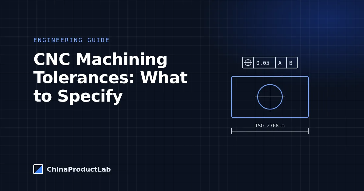
A general tolerance block covers every dimension without an individual tolerance. The most widely used is ISO 2768-1 (linear and angular dimensions). Class “m” (medium) suits most machined parts; class “f” (fine) for precision parts.
| Nominal size (mm) | ISO 2768-f (fine) | ISO 2768-m (medium) |
|---|---|---|
| 0.5 – 3 | ±0.05 | ±0.1 |
| over 3 – 6 | ±0.05 | ±0.1 |
| over 6 – 30 | ±0.1 | ±0.2 |
| over 30 – 120 | ±0.15 | ±0.3 |
| over 120 – 400 | ±0.2 | ±0.5 |
| over 400 – 1000 | ±0.3 | ±0.8 |
Write it in the title block, e.g. “General tolerances ISO 2768-mK” (the second letter covers geometrical tolerances per ISO 2768-2).
Tighten only functional features
- Bearing seats, shafts and press fits — use ISO fit classes rather than ad-hoc ± values
- Mating faces and locating pins that position other parts
- Sealing surfaces (O-ring grooves, gasket faces)
- Hole patterns that must align with another part
As a rough guide, standard CNC work commonly holds around ±0.05–0.1 mm without special effort; tolerances in the ±0.01–0.02 mm range are achievable but usually need slower finishing passes, temperature control, grinding or extra inspection — and cost accordingly. Confirm with the supplier for your material and geometry.
Use GD&T for what ± cannot express
Plus/minus tolerances control size; they do not control form or relationships. Geometric dimensioning and tolerancing (GD&T, ISO GPS or ASME Y14.5) states what actually matters:
| Requirement | GD&T control | Example |
|---|---|---|
| Surface must be flat for sealing | Flatness | Gasket face |
| Holes must line up with the mating part | Position (to datums) | Bolt pattern |
| Two bearing bores on one axis | Coaxiality / runout | Gearbox housing |
| Face square to an axis | Perpendicularity | Motor mounting face |
Define datums the way the part is located in assembly. Without datums, position and orientation tolerances cannot be inspected consistently.
Surface finish
Specify roughness (for example Ra values) only where it matters: sliding, sealing or cosmetic surfaces. A typical as-machined finish is often around Ra 3.2 µm; finer values such as Ra 1.6 or 0.8 µm take extra passes or secondary operations. Remember that coatings change dimensions — see aluminum finishes.
Make every requirement inspectable
- Mark critical-to-quality (CTQ) dimensions so the inspection report covers them
- State whether dimensions apply before or after finishing
- Avoid tolerances tighter than the measuring equipment can verify
- For GD&T features, agree the inspection method (e.g. CMM) in advance
Tolerance choices are one of the biggest CNC cost drivers. Send your drawing and we will flag tolerances that drive cost without adding function.